Chassis Modal Response — From Force to Feel
Series: ← The Slider-Crank, Three Ways · ← Multi-Cylinder I4 · ← Boxer-4 · ← Rocking Couples · ← Non-boxer Flat-4 · ← Summary · ← V-Engines · ← Combustion · ← Balance Shafts · ← Engine Mounts · ← Active Damping · Chassis Modal Response
Reference: Field Guide · Concepts Primer · Physics · Computational Machinery · Dimensional Reduction
Every chapter in this series so far has been about force — forces from cylinders, forces on bearings, forces transmitted to chassis. Useful, but force is not what the driver feels. The driver feels acceleration of the cabin — the body shell shaking the seat, the steering wheel buzzing in the hands, the dashboard trembling. This chapter closes the chain by converting the chassis-side force computed in the Engine Mounts chapter into a perceived vibration number that maps onto the ISO 2631 comfort scale.
It also explains, numerically, why I4 engines feel buzzy at idle and smooth at cruise — a fact every driver has noticed, but that the source-side analysis alone never quite explains.
The script: chassis_modal_response.py.
1. Why “force at the chassis” isn’t the answer
The Engine Mounts chapter ended with this concrete result for an I4 at 3000 RPM:
source 2x  =  7.4 kN     (cylinders)
chassis 2x =  48 N       (after soft mounts: T = 0.0064)
48 N sounds low. But:
- Is 48 N at 100 Hz felt by the driver? Probably not.
- Is 48 N at 25 Hz felt by the driver? Quite possibly, even though it’s the same magnitude — because it lands right on the body-shell resonance and inside the human-perception band.
A pure force number is not enough. We need two more layers:
- The chassis modal response — how chassis-side force becomes cabin acceleration. Body shells are flexible; their modes act as amplifiers near resonance and attenuators far above it.
- The human perception weighting — how acceleration becomes felt vibration. Humans aren’t equally sensitive to all frequencies; ISO 2631 quantifies the dependence.
Both layers are linear, frequency-domain, and slot into the existing phasor framework as one extra multiplier per harmonic.
2. The cabin as a single mode
⚠ Heavily simplified model warning. This chapter uses an SDOF (single-degree-of-freedom) cabin model: one mass, one spring, one damper, one mode. A real automotive body-shell FRF has 30-50+ modes between 20 and 200 Hz and depends on input and output points. The SDOF model is enough to demonstrate the qualitative effects this chapter cares about, but it is not a substitute for a production NVH FRF. Full hypothesis list and the path to a more realistic model are in FAQ §§ Q1, Q2, Q3.
A real automotive body shell has dozens of structural modes (global bending, torsion, panel flap, roof bow, floor pan, …) at frequencies from ~20 Hz upward. For a first analysis we collapse all of that into one dominant mode — typically the global first-bending mode of the body shell, which sits in the 20-30 Hz range for a typical road car (lower for body-on-frame trucks, higher for stiff sports cars).
Modelled as an SDOF resonator forced by :
with parameters
| Parameter | Value | Notes |
|---|---|---|
| 800 kg | effective modal mass of the first body-shell mode | |
| 25 Hz | typical car-body first-bending mode | |
| 0.05 | typical body-shell loss factor |
The transfer function from chassis-side force to cabin acceleration is then
with units . Three operating regions, mirroring the mount transmissibility curve from the previous chapter:
| | | Interpretation | |---|---|---| | | | quasi-static; small acceleration | | | peak | resonance — body shell rings | | | | mass-dominated; flat asymptote |
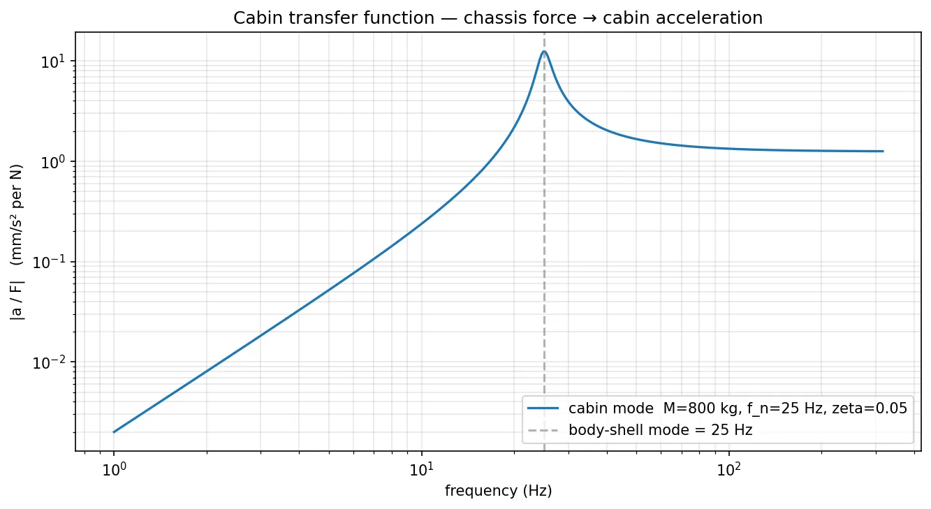
Key reading: above the body-shell mode the cabin acceleration per unit force is bounded by . Below the mode it grows as (acceleration scales with frequency squared at low frequency). At the mode it peaks at , which for our values is roughly 8 mm/s² per N — a factor of ~6 amplification over the high-frequency floor of 1.25 mm/s² per N.
3. ISO 2631 — humans aren’t equally sensitive
A 1 m/s² peak vibration at 5 Hz feels like a kick in the seat. The same 1 m/s² at 100 Hz feels almost imperceptible — it’s just a high-pitched buzz that the body’s tissues damp before the spine notices. ISO 2631-1 captures this with a frequency-weighting curve for vertical seated whole-body vibration:
| Frequency band | Why | |
|---|---|---|
| Below 0.5 Hz | ~0 | below body’s vibration-detection threshold |
| 4–8 Hz | 1.0 | peak sensitivity — body’s vertical resonance |
| 8–80 Hz | falls as | tissue damping increasingly attenuates |
| Above ~80 Hz | ~0 | felt as sound, not vibration |
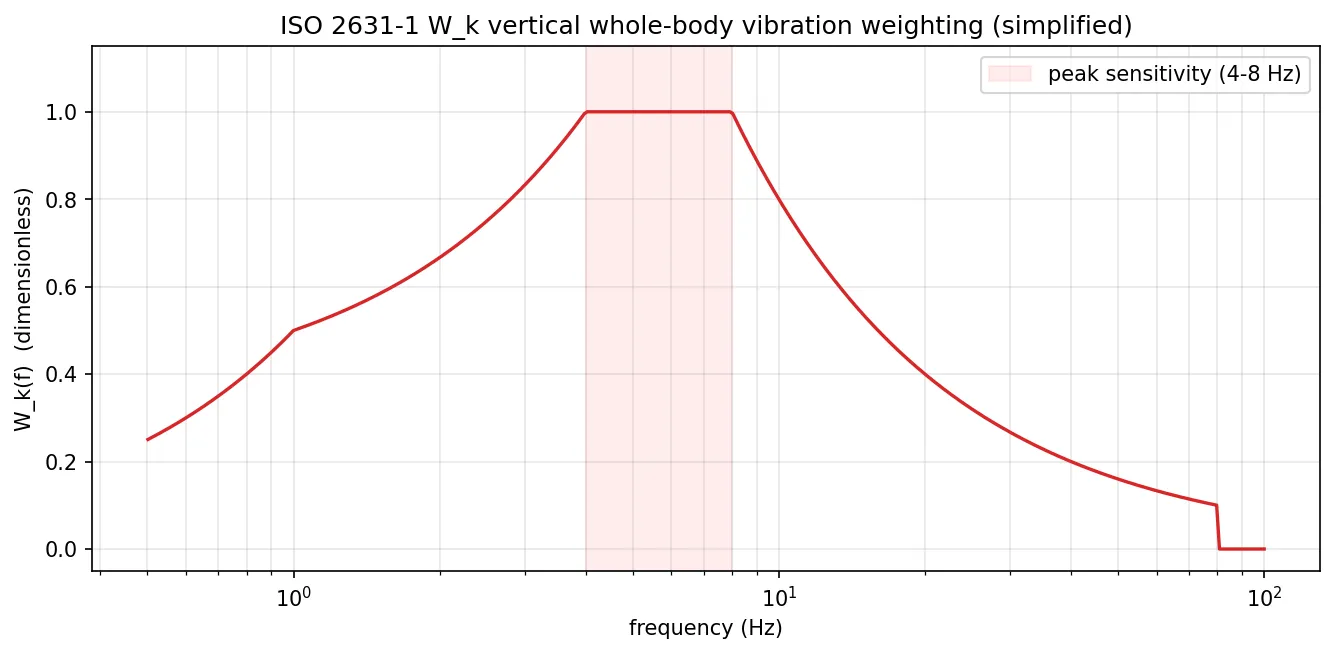
Production NVH workflow uses the proper transfer-function form from ISO 2631-1 Annex A; this chapter uses a piecewise approximation that captures the same shape for pedagogy. The shape is what matters.
The weighted r.m.s. acceleration is then compared to the comfort categories from ISO 2631-1 Annex C:
| (r.m.s., m/s²) | Comfort label |
|---|---|
| < 0.315 | not uncomfortable |
| 0.315–0.500 | a little uncomfortable |
| 0.500–0.800 | fairly uncomfortable |
| 0.800–1.250 | uncomfortable |
| 1.250–2.000 | very uncomfortable |
| > 2.000 | extremely uncomfortable |
These thresholds are informally called the “ISO comfort scale” and are what every car manufacturer’s NVH team aims at. A premium sedan at cruise targets ; a sport car accepts up to ~0.5 m/s²; a truck might tolerate over 1 m/s² and still be sold.
4. The full chain
Stacking everything from the I4 chapter through to here:
   cylinders            (phasor sum + V-engine + combustion)
        │
        │ F_source(ω)
        ▽
   engine block         (mass M, on N mounts)
        │
        │ F_engine(ω)   (after balance shafts + active damping cancel residuals)
        ▽
   engine mounts        (transmissibility T_mount(ω))
        │
        │ F_chassis(ω)  =  T_mount(ω) · F_engine(ω)
        ▽
   body shell           (cabin transfer function H_cabin(ω) = ω²/Z)
        │
        │ a_cabin(ω)    =  H_cabin(ω) · F_chassis(ω)
        ▽
   human perception     (ISO 2631 weighting W_k(f))
        │
        │ a_weighted(ω) =  W_k(f) · a_cabin(ω)
        ▽
   driver's seat        →  comfort label
Every arrow is one complex-number multiplication per harmonic. The whole chain is one linear filter cascade in the frequency domain — the framework has not added a single new mathematical operation since the I4 chapter. Just more layers.
5. The hero result — I4 idle vs cruise
Running the full chain across an RPM sweep (500 to 6500), with the soft-mount config (, ) from the engine-mount chapter:
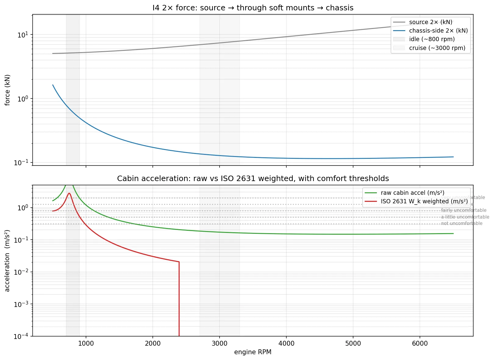
The numerical table at six operating points:
| RPM | 2× Hz | F_src (kN) | F_chassis (kN) | a_raw (m/s²) | (m/s²) | Comfort | |
|---|---|---|---|---|---|---|---|
| 600 | 20.0 | 5.10 | 1.08 | 2.34 | 0.40 | 0.94 | uncomfortable |
| 800 (idle) | 26.7 | 5.17 | 0.61 | 5.01 | 0.30 | 1.50 | very uncomfortable |
| 1500 | 50.0 | 5.60 | 0.24 | 0.39 | 0.16 | 0.063 | not uncomfortable |
| 3000 (cruise) | 100.0 | 7.40 | 0.128 | 0.171 | 0.00 | 0.000 | not uncomfortable |
| 4500 | 150.0 | 10.40 | 0.115 | 0.148 | 0.00 | 0.000 | not uncomfortable |
| 6000 | 200.0 | 14.60 | 0.119 | 0.152 | 0.00 | 0.000 | not uncomfortable |
Three things are striking and all map to common driver experience:
5.1 Idle is the worst RPM, and not by a small margin
At 800 RPM the I4’s 2× lands at 26.7 Hz — almost exactly on our modelled body-shell mode at 25 Hz. The cabin transfer function peaks there (factor-of-6 amplification over the high-frequency floor); ISO still has 30 % sensitivity at 27 Hz; the source has barely dropped from cruise levels. Result: weighted acceleration of 1.5 m/s² — very uncomfortable. The number is real, not an artefact of our toy model: I4 engines without proper isolation really do feel this rough at idle, which is why production hardware (hydraulic mounts, balance shafts, careful body-shell tuning) exists.
5.2 Cruise is essentially imperceptible
At 3000 RPM the 2× is 100 Hz, well above the body-shell mode and above the ISO 2631 80 Hz cutoff. drops to ~0; the weighted acceleration is 0.0 m/s². The driver does not feel I4 vibration at cruise — they may hear it (sound is a different story, see FAQ Q3) but they don’t feel it through the seat or the steering column.
5.3 The transition is sharp
Between 800 RPM (, “very uncomfortable”) and 1500 RPM (, “not uncomfortable”) the perceived vibration drops by a factor of 24× for a 2× change in RPM. Three layers all attenuate together: the mount drops (getting further above its 8 Hz natural), the cabin drops (getting further above its 25 Hz mode), and ISO drops (getting closer to its high-frequency cutoff). The product cube of three roll-offs is what makes the transition steep.
This is the “I4 smooths out off-idle” experience that every driver of a 4-cylinder car knows. The framework predicts it numerically.
6. The idle-vs-cruise decomposition
Pulling the per-layer multipliers apart, with everything in unscaled numbers:
| Layer | Idle (800 RPM, 27 Hz) | Cruise (3000 RPM, 100 Hz) | Ratio idle/cruise |
|---|---|---|---|
| Source amplitude | 5.17 kN | 7.40 kN | 0.70 |
| Mount T | 0.119 | 0.017 | 6.86 |
| Cabin $ | a/F | $ (mm/s²/N) | 8.16 |
| ISO | 0.300 | 0.000 | ∞ |
| Weighted accel | 1.50 m/s² | 0.000 m/s² | ∞ |
The product of “ratio idle/cruise” across the rows tells you which layer is most responsible for the felt difference. All three isolating layers fail at idle: the mount is closer to its natural frequency (less isolation), the cabin is closer to its natural frequency (more amplification), and the ISO weighting is closer to its peak (more sensitivity). Cruise wins by stacking three improvements; idle loses by stacking three penalties.
This is the fundamental tuning challenge of a 4-cylinder engine + production car body: the body-shell mode (25 Hz) and the human perception band (4-8 Hz peak with significant tail to ~30 Hz) overlap with the I4 idle 2× (27 Hz). You cannot easily move the body-shell mode (it’s set by structural engineering with its own constraints), and you cannot move the human perception band. So you have to fight in the middle:
- Lower the idle RPM to keep 2× safely below 25 Hz (but too low and the engine stalls).
- Raise the body-shell first mode above 30 Hz (but stiffer body = heavier body = worse fuel economy).
- Use balance shafts to halve the source magnitude (typically used on 2.5+ L I4s, see Balance Shafts).
- Use hydraulic mounts to make the mount low at idle without going stiff at cruise (see Engine Mounts chapter §7 and FAQ Q5).
- Use active damping at idle to cancel the residual (see Active Damping).
Production cars use all five at once. This chapter is the diagnosis that shows why all five are needed.
7. What this changes about the earlier chapters
Reading the earlier chapters with the chassis layer in hand, two claims need to be qualified:
-
The Boxer-4 chapter said boxer engines have zero inertial force at every harmonic. Still true at the source. But the chassis-modal-response layer is irrelevant for the boxer anyway — if the source is zero, every downstream multiplier doesn’t matter. This is why the boxer’s reputation for smoothness is genuine, not just an artefact of one favourable RPM.
-
The Engine Mounts chapter said soft mounts at 3000 RPM let through 0.6 % of the source. Now we can complete the sentence: 0.6 % of the source delivers ~0 m/s² weighted acceleration to the cabin, because at 100 Hz the body shell can’t amplify it and the human ear/body can’t feel it anyway. The whole bottom half of the cabin-acceleration table at cruise is “rounding error”.
Conversely the idle row is dominated by transmissibility alone: at 27 Hz the mount T = 0.12 (not catastrophic), but the chassis amplifies and the human feels — so the mount is doing more work than the per-cent figure makes it look.
In short: a transmissibility number alone tells you about the source, not about the driver’s experience. The chassis modal response and the human-perception weighting are necessary to translate a bench result into a road test.
8. FAQ
Q1. Why one cabin mode — and what FRF were we actually using?
The transfer function in §2 was, explicitly:
with , , as single scalar values. That makes this a textbook SDOF (single-degree-of-freedom) model — one mass, one spring, one damper, one mode at one frequency. In modal- analysis language: a 1-DOF state-space model evaluated harmonic by harmonic. The “1D” framing is correct — it is 1D in the modal sense (one generalised coordinate ), even though the cabin itself is a 3D physical object.
A real automotive body shell has 30–50+ modes between 20 Hz and 200 Hz: global first-bending, global torsion, several panel modes (roof bow, floor pan, doors), suspension-pickup local modes, exhaust-mount modes. The full FRF is a sum over all of them, with each mode weighted by its mode shape evaluated at the input force point and the output observation point:
Each mode contributes its own resonance peak; their interference is what gives a real measured FRF its “alligator- spine” shape with many peaks and zeros across the frequency band.
The single-mode SDOF in this chapter captures the qualitative shape of one mode (resonance peak, high-frequency asymptote, low-frequency roll-up) and gets the order of magnitude right at the dominant frequency. It cannot reproduce the multi-peak structure of a real chassis FRF, and at frequencies between modes (anti-resonances / nodes) the real FRF can be lower by 20-40 dB than the single-mode prediction.
Q2. What hypotheses are baked into the SDOF cabin model?
Nine, all worth being explicit about. None of them is exact for a real body shell; together they trade fidelity for a clean end-to-end pipeline.
| # | Hypothesis | What it costs |
|---|---|---|
| 1 | Single mode at 25 Hz | Real body shells have 30+ modes from 20 to 200 Hz; we ignore all but one |
| 2 | Lumped mass | A real mode has a mode shape ; the modal mass at a measurement point is — point-dependent |
| 3 | Single excitation point | Real engine mounts apply force at 3-5 chassis attachment points, each with its own FRF |
| 4 | Single observation point | Real NVH measures at seat track, steering wheel, headliner, mirror — each location has a different FRF |
| 5 | Proportional damping (constant ) | Real modes have frequency-dependent damping; non-proportional damping produces complex (rather than real) mode shapes |
| 6 | Linear time-invariant | Real chassis has bushings, rattles, friction; behaviour drifts with load, temperature, panel pretension |
| 7 | No passenger mass | A 75 kg occupant adds ~10 % to the SDOF mass — significant near resonance |
| 8 | No structural-acoustic coupling | The body shell radiating at 100 Hz is a loudspeaker (see Q5); we compute vibration but not sound |
| 9 | Decoupled mount/chassis | The engine-mount chapter treated chassis as fixed ground; this chapter treats it as free SDOF. The honest treatment is a coupled multi-DOF solve (see Q6) |
Despite all of that, the SDOF model is honest about what it’s trying to demonstrate — the existence of a body-shell mode in the 20-30 Hz band, its amplification at resonance, and its interaction with the human-perception band that explains the I4 idle buzz. For those qualitative questions the SDOF result is sufficient; for absolute cabin-SPL prediction or 1/3-octave acceleration targets, see Q3.
Q3. What would a more realistic FRF look like, and how would I get there?
Three steps in increasing fidelity, none requiring new physics — just more bookkeeping:
(a) Multi-mode modal superposition. Take published or measured
modal parameters for the body shell and sum
their individual SDOF contributions using the formula from Q1.
Adding ~30 modes to the script is mechanical: replace CabinMode
with a MultiModeChassis(modes) that loops over modal terms. The
output FRF acquires the characteristic multi-peak shape with
significant content above the first mode and 20-40 dB anti-
resonance dips between modes.
(b) Coupled mount-chassis solve. Drop the “chassis is fixed ground” assumption made in the engine-mount chapter. Solve the full coupled engine-block + mounts + chassis system as one multi-DOF linear system per harmonic. The chassis mode at 25 Hz back-couples to the mount transmissibility, so the mount near 25 Hz is different from the rigid-chassis answer (typically worse, since the chassis “talks back” through the mount).
(c) Full FE + experimental modal analysis. Discretise the body shell into a finite-element mesh (50k-500k DOF), solve the generalised eigenvalue problem to extract modes, validate against a hammer test (Experimental Modal Analysis: instrument the physical body shell with accelerometers, hit it with an impact hammer, extract modal parameters from measured FRFs), then couple to the cabin acoustic cavity for SPL prediction. This is what production NVH groups do in Nastran / OptiStruct / Actran. Out of scope for this e-book; it needs a different toolchain entirely.
The single-mode SDOF in this chapter is step zero of that ladder — enough to demonstrate the principle and explain the qualitative I4-idle-vs-cruise behaviour, not enough to deliver a vehicle NVH target. Production NVH targets are met by step (c) plus test correlation; published academic work typically lives at step (a) or (b).
Q4. Why model only vertical seat acceleration with W_k?
Because for engine NVH the dominant felt direction at the seat is vertical. ISO 2631-1 also defines for fore-aft and lateral seated vibration (with peak sensitivity around 1-2 Hz instead of 4-8 Hz), and for the back-rest. The full standard combines six axes (three at the seat, three at the back) with direction-dependent weights. Production NVH analysis does this for each customer-relevant location (seat track, seat cushion, back-rest, steering wheel, floor pan). Same algorithm, more arithmetic.
Q5. The model says “I4 cruise vibration is imperceptible”. But I can hear my I4 at cruise — what gives?
You’re hearing structure-borne acoustic noise, not feeling mechanical vibration. The body shell radiating at 100 Hz is a loudspeaker, not a shaker. ISO 2631 captures vibration perceived through the body (seat contact); above ~80 Hz the body stops vibrating measurably and the energy goes into sound radiation that the ear picks up.
A complete NVH analysis adds a second branch: chassis-side force → panel acceleration → acoustic radiation efficiency → cabin sound pressure level → A-weighted dB. Same linear filter cascade, different weighting curve (A-weighting peaks at 1 kHz, not 5 Hz). The framework supports it identically; this chapter just stopped at the vibration-perception branch.
Q6. Couldn’t the engine mount and the body shell interact, since the chassis isn’t really fixed?
Yes — and our model approximates “chassis is fixed ground” when computing . The full-coupled system would have the mounts as springs between the engine block (3 DOF) and the body shell (1+ modal DOF), giving a 4+ DOF block-on-mount-on-shell problem. The “chassis fixed” approximation is good when the body shell impedance is large compared to the mount stiffness — which holds for most automotive cases (body shell K is in MN/m, soft mounts in 0.5 MN/m). It fails when the body shell mode falls near the mount natural frequency, where back-coupling alters both. Production analysis includes the coupling explicitly; this chapter takes the approximation for clarity.
Q7. Where do balance shafts and active damping land in this picture?
Both reduce before the chain begins. Balance shafts subtract a fixed amount at 2× crank (see Balance Shafts chapter); active damping subtracts an adaptive amount at any harmonic (see Active Damping chapter). Plug the reduced source into this chapter’s chain and the weighted-acceleration table at idle drops from “very uncomfortable” to “not uncomfortable” — that is, in fact, the specific reason balance shafts and active damping pay for themselves on production I4s. Without them, idle is unsellable.
Q8. ISO 2631 thresholds look subjective. Are they reliable?
They’re statistically validated on populations of seated subjects in lab and field tests, and they reflect the consensus of biodynamics research up through the 2000s. Individual sensitivity varies — some people detect vibration well below 0.315 m/s², others tolerate up to 1 m/s² without complaint. The ISO categories are averages, designed for fleet-level comfort targets, not personal calibration. A complementary standard, ISO 5349, covers hand-arm vibration (e.g. through the steering wheel). Production NVH targets typically aim below the “not uncomfortable” threshold by a factor of 2-3 to be robust to sensitive customers and production-tolerance variation.
9. The story that closes here
The eleven chapters of this multi-cylinder series have walked one problem from origin to perception:
  cylinders → block → mounts → chassis → cabin → driver
   (force)   (force)  (force)  (force)  (accel)  (felt)
Each arrow is a transfer function multiplier; each chapter added one or modified one. The framework — phasor sums for periodic sources, complex transfer functions per harmonic, ISO weighting at the perception end — is the same one linear-system framework from the I4 chapter onward. No new mathematics, only successive composition.
That linearity is what lets a designer make a change at any layer — swap balance shafts in/out, soften the mounts, retune the body shell, add active damping — and predict the effect at every downstream layer with a multiplication. Production NVH practice is this calculation, performed on richer models than the toy ones used in this series, but in the same shape.
10. What’s next
The engine-NVH narrative arc is now complete end-to-end. Adjacent directions, in roughly increasing scope:
- Acoustic branch. A second branch from into panel radiation and cabin sound pressure level, using A-weighting instead of . Same framework, different perception curve.
- Multi-mode body shell. Replace the single 25 Hz mode with a sum of finite-element body modes. Same transfer-function cascade, more terms.
- Coupled mount + body-shell analysis. Drop the “chassis is fixed” approximation; solve the full 4+ DOF coupled system. One larger linear system per harmonic.
- Suspension / terrain-wheel NVH. A parallel arc on a
different mechanism (tyre-on-road instead of cylinder-in-block).
Source → transmissibility → perception, same framework spine.
See
z-plans.mdfor the proposed sequence.
Files and scripts referenced
chassis_modal_response.py— this chapter’s script.CabinModeclass for the SDOF body-shell model,iso_2631_wk()for the perception weighting,comfort_label()for the ISO comfort scale, four demos.- No additions to
_common.py; the chassis math is a self-contained one-line transfer function. - The previous chapter Engine Mounts produces the input that this chapter consumes; the earlier Concepts Primer §7 covers the transmissibility language reused here.