The Boxer-4 — Why Opposed Pistons Cancel Everything
Series: ← The Slider-Crank, Three Ways · ← Multi-Cylinder I4 · Boxer-4 · Rocking Couples → · Non-boxer Flat-4 → · Summary → · V-Engines → · Combustion → · Balance Shafts → · Engine Mounts → · Active Damping → · Chassis Response → · Engine Mounts →
Reference: Field Guide · Concepts Primer · Physics · Computational Machinery · Dimensional Reduction
A direct sequel to Multi-Cylinder by Superposition — the Inline-Four.
The I4 story ended with a punchline: primary cancels, secondary quadruples. This chapter changes one variable — physical orientation of half the cylinders — and watches the entire inertial spectrum collapse to zero. No primary, no secondary, no anything. The boxer configuration is, in pure-force terms, inherently balanced at every harmonic.
The script that produces every number and figure below is
boxer4_analysis.py.
It runs in three seconds and reuses the same single-cylinder
simulation we’ve been carrying since the inverse-dynamics chapter.
1. The geometry that makes a boxer
A horizontally-opposed (boxer) flat-4 has its cylinders arranged in two pairs on opposite sides of the crankshaft:
         CYL 2 (left bank)              CYL 1 (right bank)
    ----[ piston ]----+              +----[ piston ]----
                      ↑                                 ← cyls 1 & 2 are at the SAME
                      crank pin 1 (cyl 1)                 kinematic phase: when pin 1
                      crank pin 2 (cyl 2)                 is at TDC for cyl 1, pin 2
                                                          is at TDC for cyl 2.
                                                          Both pistons "kick out"
         CYL 4 (left bank)              CYL 3 (right bank)  of the engine simultaneously.
    ----[ piston ]----+              +----[ piston ]----
                      ↑                                 ← cyls 3 & 4 are at the same
                      crank pin 3 (cyl 3)                 kinematic phase as each other,
                      crank pin 4 (cyl 4)                 offset 180° from cyls 1 & 2.
A real boxer crankshaft uses four separate crankpins (one per connecting rod), not two shared ones — splitting the pins this way keeps the cylinder bores nicely opposed in line, which a true V-style shared pin couldn’t do. The kinematic upshot is identical to a “two shared pin” idealisation: cylinders 1 and 2 are phased identically on the crank (same crank angle puts both pistons at their respective TDCs), and likewise cylinders 3 and 4. So the four kinematic phases collapse to two: 0° and 180°. That’s the property that drives the cancellation; the literal pin count doesn’t matter.
When the cylinder-1 piston is at its TDC, so is cylinder 2’s — but those TDCs are on opposite sides of the engine, so in world coordinates the right piston is at maximum +x while the left piston is at maximum −x. They are kinematically mirror images.
That mirror-image relationship is the one additional ingredient on top of the I4 analysis. Everything else — the simulation, the phasor framework, the FFT pipeline — is unchanged.
2. Translating the mirror into the phasor sum
In the I4 chapter we established the master equation:
For the boxer we extend it with a per-cylinder sign:
where for right-bank cylinders and for left-bank cylinders. The sign flip captures the fact that a left-bank piston’s bearing-force contribution at the main bearing is the negative of the corresponding right-bank piston’s, because the left-bank piston is moving in the opposite world-x direction.
For a textbook boxer-4:
| Cylinder | Bank | Crankpin | Phase | Sign |
|---|---|---|---|---|
| 1 | right | 1 | 0° | +1 |
| 2 | left | 1 | 0° | −1 |
| 3 | right | 2 | 180° | +1 |
| 4 | left | 2 | 180° | −1 |
The phasor sum at any harmonic :
This is identically zero for every n. Not zero up to approximation, not zero in the small- limit, but exactly zero for every harmonic from DC to infinity. The physics is just that opposed cylinders sharing a crankpin always generate exactly equal and opposite bearing-force contributions, no matter how complicated each one’s individual harmonic content might be.
3. The phasor picture
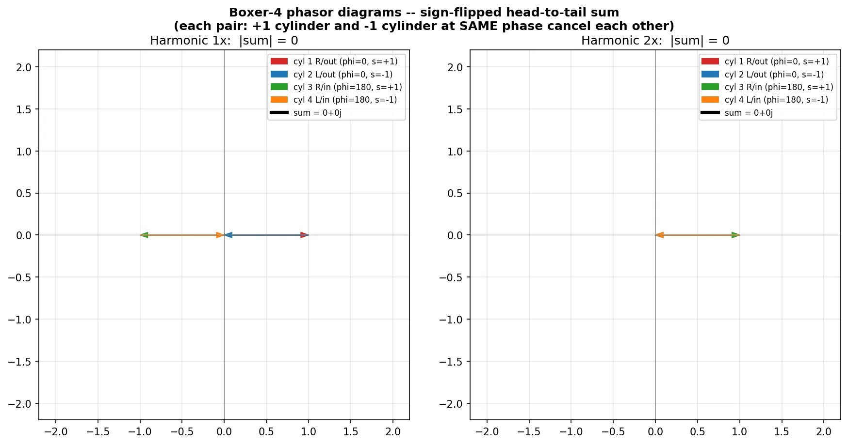
At every harmonic the four arrows split into two opposing pairs at the same phase: cylinder 1’s and cylinder 2’s are anti-parallel in the complex plane and close immediately back to the origin; cylinder 3 and cylinder 4 do the same at the other phase. Two zero-vectors stack on top of each other. Sum = origin.
Compare with the I4’s phasor diagrams in the previous chapter: at 2× the I4 had four arrows aligned head-to-tail, climbing to length 4. The boxer’s 2× diagram, by contrast, looks like two collinear pairs of opposing arrows — visually zero from the start.
4. The measured spectrum and the smoothness theorem
The script computes the phasor-sum magnitudes side-by-side with the I4, then verifies them against the time-domain superposition:
| n | I4 |Σ| | Boxer-4 |Σ| |
|---|---|---|
| 0 | 4.000 | 0.000 |
| 1 | 0.000 | 0.000 |
| 2 | 4.000 | 0.000 |
| 3 | 0.000 | 0.000 |
| 4 | 4.000 | 0.000 |
| ≥5 | (alternates) | 0.000 everywhere |
And every measured spectrum amplitude matches:
| n | Rx single (gravity off) | Rx I4 | Rx Boxer-4 |
|---|---|---|---|
| 1× | 9.87 N | 0.24 N* | 0.000000 N |
| 2× | 4.11 N | 16.44 N | 0.000000 N |
| 4× | 0.295 N | 1.18 N | 0.000000 N |
| 6× | 0.024 N | 0.095 N | 0.000000 N |
*See the next section for why the boxer column is cleaner than the I4 even at the residue level.
The full spectrum bar chart with all three configurations side by side:
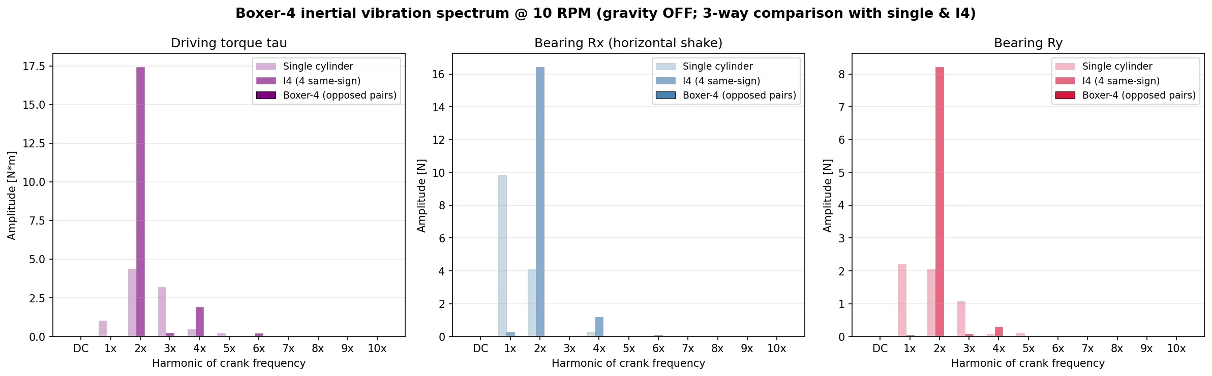
Bold dark bars on the right of each cluster are the boxer-4 — they sit on the x-axis. The faint left bars are the single-cylinder reference; the medium-shade middle bars are the I4 sum (with its characteristic 4× secondary peak).
In the time domain:
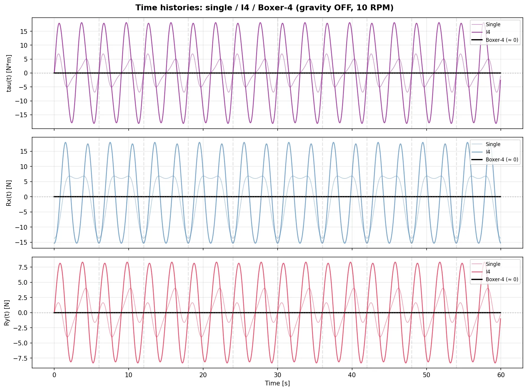
The boxer-4 trace (black) is a flat horizontal line at zero through all 10 revolutions, for , Rx(t), and Ry(t) alike. Single (faint) and I4 (colored) wiggle in the background for comparison.
That’s the boxer smoothness theorem: in a force sense, you cannot build a more balanced engine than a horizontally-opposed pair-of-pairs.
5. A numerical-purity bonus
In the I4 chapter we noted a tiny 0.24 N residual at 1× — an artefact
of samples_per_rev = 102.4 rounded to 102 in np.roll. The boxer-4
result has no such residue. Why?
In the I4, the cancellation at 1× depends on a 180° time shift
(cylinders 1, 4 cancel cylinders 2, 3 because they’re shifted by half
a revolution in time). When samples_per_rev is non-integer, the
shift rounds and the cancellation isn’t perfect.
In the boxer, the cancellation is between cylinders at the same
phase (cyl 1 and cyl 2 are both at phase 0°; cyl 3 and cyl 4 both
at 180°). They cancel via the sign flip before any time shift is
applied. There’s no np.roll between the cancelling cylinders, so
no rounding error enters. The result is exactly zero to the
machine-precision floor.
This is a small but pleasing bonus that falls out of the geometry — it’s also a useful hint that real engineers should prefer configurations where the cancellation mechanism is sign-flip rather than phase-shift, when both options exist.
6. What the boxer does not cancel
The result above is the textbook smoothness story, but it has a caveat that’s important enough to spell out:
Force balance ≠ moment balance.
The four cylinders in our analysis are treated as colocated at x = 0 along the crankshaft. In a real boxer-4, cylinder pair 1+2 sits at some position along the crankshaft (call it ) and pair 3+4 sits at the other end (). The pairs separately produce zero net force, but they sit at different x-positions on the shaft. So the bank’s center-of-pressure of the inertial-force system is not at the geometric centre — and that produces a rocking couple about the engine’s vertical axis, oscillating at 2× crank frequency.
In moment-sum terms:
For our boxer with positions (each pair colocated):
So the moment also cancels for a boxer-4 with colocated opposed pairs — which is to say, when the two pairs are perfectly stacked. But real engines have offset crankpins (small between paired cylinders), and a real boxer-4 with that small asymmetry develops the 2× rocking couple that gives Subaru engines their distinctive 2× hum at idle. That’s outside force-only analysis but it’s the same phasor machinery — just multiply by before summing.
The next chapter in this progression will pick up moments explicitly. For now: the force analysis is complete, and the result is genuinely beautiful.
7. The punchline in one sentence
A boxer engine cancels every inertial harmonic at the main bearing because mirror-image piston motion turns superposition into a sign-flipped phasor sum, and any pair of opposed cylinders sharing a crankpin sums to exactly zero — independent of harmonic number, rod ratio, or RPM.
Verified by running one cylinder once, summing four phase-and-sign
combinations, and printing the result:
max|Rx(t)| = 0.000000 N.
8. Where this leads
- Non-boxer flat-4: opposed cylinders but with crankpins NOT shared (so paired cylinders have different phases). Some harmonics cancel via signs, others don’t. The Lancia Fulvia flat-4 is a historical example.
- Moment / rocking-couple analysis: . The same script with one extra weighting per cylinder catches the rocking signature that pure force analysis misses.
- V6, V8, straight-6: each one is a different recipe of phases and signs. A straight-6 with phases at 60° intervals cancels forces AND moments at 1× and 2× — that’s why straight-6 engines (BMW, Mercedes, Jaguar) feel uncanny-smooth without any external balancer hardware.
All of these reuse the same _common.py helpers. None of them
require running a new dynamics simulation. The investment in the
single-cylinder simulation pays off again every time a new
configuration is added.
Files and scripts referenced
boxer4_analysis.py— boxer-4 superposition with sign flip; produces all three figures above._common.py— shared helpers, now with optionalsigns=argument onsuperpose_time()andphasor_sum().README.md— the folder’s orientation, including the “what’s next” roadmap.
Prerequisite chapters:
- The Slider-Crank, Three Ways — single-cylinder inverse dynamics, vibration FFT, gravity-isolation experiment.
- Multi-Cylinder by Superposition — the Inline-Four — establishes the phasor framework that this chapter extends with signs.